
The Feasibility and Pre-design phases of architectural design have been about finding information and establishing parameters. Schematic design is the process by which we use that information to generate a project design. We think this is the fun part of the project where the magic happens! However, the process can be difficult to explain.
The Design Process
The design process is unique to each designer and may additionally vary from project to project. However, the process often starts with the site. We will sit down with the survey and identify site access, contours, solar access, views, setbacks, privacy, etc. These will give us an idea of the best location for the structure, where the main entry will be, which parts of the structure will be opaque, and which parts want to be transparent. All of this is then sketched (electronically or with traditional media) over the survey.
Bubbles!!!
Next, we turn to the programming information provided by the owner. How do the owner’s wants and needs fit within the site constraints previously identified? This leads to another layer of sketching over the survey often in the form of a bubble diagram. With the bubble diagram, we have a basic map of the project that responds to site restraints and opportunities, identified spatial or functional relationships between uses, and a framework for ensuring the broad strokes of the program are being met, but there is likely something missing. We will refer back to the code summary, consultant reports, and other elements generated during pre-design, then revise and refine the work. This is an iterative process with many layers of sketches and collaboration with our colleagues to revise and refine the work, until the bubbles give way to rooms, spaces, and ultimately a preliminary floor plan.
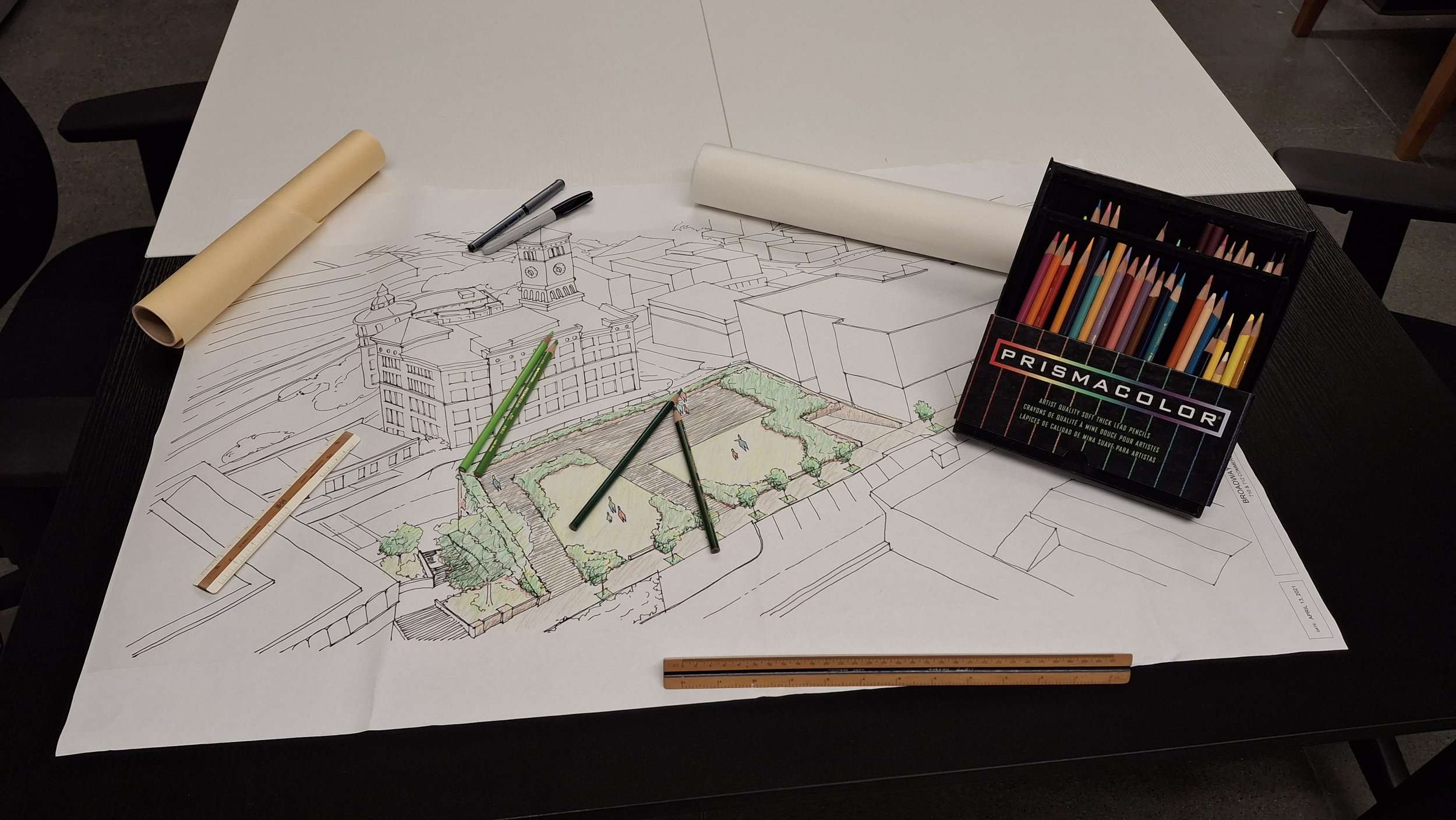
Schmatic Design sketch for a client presentation.
Three Dimensions
The right floor plan is important, but a great space is more than an extrusion of the floor plan, and considering the design in three-dimensions is best done early and in tandem with the plans. A great floor plan does not necessarily lead to a great three-dimensional piece of architecture, just as a beautifully sculpted form may be difficult to live with if a functional plan doesn’t fit. We start thinking about the building form with the client’s program in mind: Do they want a single-story home or multiple levels? Do we want a basement to meet their needs or to take advantage of a slope? During the bubble diagram phase of the project, we will work back and forth with three-dimensional sketches. These may be hand sketches, digital three-dimensional models or a combination of the two. Initially, the three-dimensional models might be a series of white boxes, but over time it begins to illustrate the look and feel of the project, including materials. Once we believe we have a good solution that meets the needs of the clients we set up a client meeting.
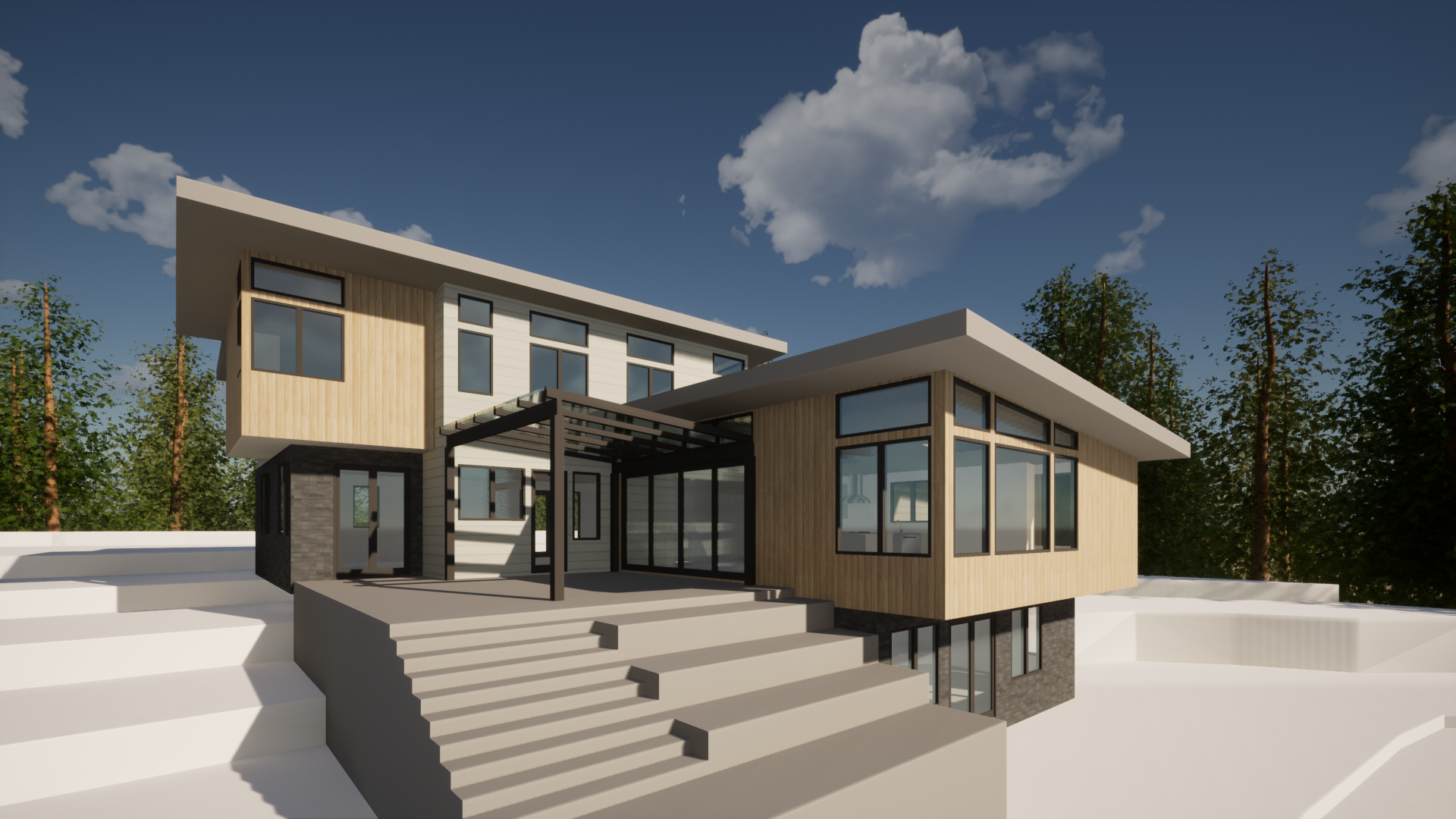
Schematic Design Sketchup model for cleint presentation.
Client Meeting
We work collaboratively with our clients throughout the process. The initial conversations, Pre-Design meetings, and sharing of information to form the program, all set the stage for the design work. The initial schematic design meeting is our opportunity to meet with the client and talk through our design proposal and the design documents. We love to sit at a table with a roll of trace paper to sketch out small changes or help explain a detail, often making changes or solving problems in the moment that might take days of back and forth over email or video conferencing. What we present at the initial design meeting depends on the client as well as the project, but typically includes: a site plan, floor plans, and the three-dimensional model with views and 2D elevation images taken from it. We take the feedback from this meeting back to the drawing board to refine the design, sharing new versions with the client (sometimes in person, sometimes via email) until we have an approved schematic design package.
Schematic Design Deliverables
The schematic design package includes the necessary documents to proceed into the Construction Documents phase of the project. These include drafted copies of a site plan, all floor plans, a building section showing how it meets the site, and exterior elevations of each building façade. CAD files of this work are shared with the other consultants on the design team to serve as background drawings over which they may do their work.
Next, the work continues as the team transforms the schematic design drawings into a more robust set of plans and files that make up the construction documents package. We will cover that in our next installment!
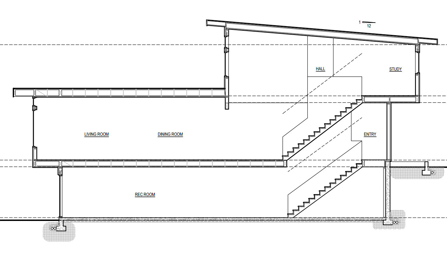
Schematic Design Section for consultant background. Note: Same house as model image above.